- Free Dota Template
- Cinematics
- Color Codes
- Dialog Boxes
- Multiboards
- Abilities - Buffs and Spells
- Abilities - Guide
- Abilities - Introduction
- Advanced Skinning in Photoshop
- AI - Basics and Triggers
- AI - The Editor
- Start Here
- General FAQ
- Cameras
- Campaign Basics
- Elevator Switches
- Formula Finder
- Unit Editor
- Trigger Basics
- Variable Basics
- Attachments
- Creating Icons
- Custom Tiles
- Editing Skins
- Fade Filters
- Importing Models
- Loading Screen
- Minimap Image


|
|
 |
 |
|
Magos' modeling TutorialDonated by Magos In this tutorial I will teach you how to make a model, texture it, animate it, add some particle emitters and attachment points, and then import it into Warcraft 3. As from 2003-11-06 Blizzard has released its own set of Art Tools, making modeling easier. These tools are however only for 3DStudio Max which is a professional tool and costs lots of $$$ (~3000$ I've heard). If you don't feel like spending that kind of money just to make a model, you can follow this tutorial.
Each part ends with a Checklist, that mentions some common errors that are made. Avoid these at all cost. If you have any questions/suggestions post them in a new thread in the Model Editing forum. I DO NOT answer questions per mail. You will need certain tools to be able to model. There are probably alternatives to the tools listed below, so if you prefer to use another then do. These tools are the ones I use, and recommend. Note that if you use another tool the tutorials might not be correct. GMax
This tool is a modeling program, and you're definitely going to need it. GMax is a lite version of 3D Studio Max, and it's FREE. So don't hesitate, go get it at Discreet's site. After getting it, I recommend following some of the tutorials that comes with it just to get a feel of how it works. I will still take up some basic concepts in the modeling tutorial below, but not all.
Dex' Exporter script
After you're done modeling, you end up with a *.gmax file, which is quite different than the MDL/MDX files used in Warcraft 3 (these are Blizzard file formats). So you need to convert it, and that's why you need an exporter script. There are several scripts out there but the only one I had any success with using is Dex' Exporter script.
After getting the script, place it in any folder where you can find it later ("C:\GMax\Scripts" for example). Yobgul's Mdl-Mdx File Converter
When using the script, you end up with a MDL file. However, you need to convert it to a MDX file before it's usable in Warcraft 3. MDL and MDX files are basically the same thing, however MDL files are in text format while MDX files are in binary format. If that doesn't make any sense to you, then skip it. It's not that important. All you need to know is that you have to convert it from MDL to MDX before importing it in Warcraft 3.
Paint Shop Pro If you want good looking textures, you need some kind of image editing program. I use Paint Shop Pro, but there are a lot of other programs out there, like Photoshop and IrfanView (FREE). If you choose another program, it must be able to save files as targa (*.tga) and support alpha channels. See our Files and Tools page to find a graphic program. Wc3 Image Extractor II
Again, Blizzard uses their own file formats. As image files they use Blizzard Pictures (*.blp). Luckily, there is a converter that converts *.tga files to/from *.blp files.
What is this? There are some important concepts in modeling that can be worth learning. To get a better understanding of how a model is made up. I will use this terminology in the tutorials down below, so it might be a good idea to learn most of them. Vertex A Vertex (plural: vertices) is a point in 3D space. It is used to keep track of the 'parts' of your model (roughly explained). Face
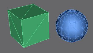
A Face is what you actually 'see' when looking at a model. It is a triangle shaped object, where its corners are attached to 3 vertices. Why triangles? Well, a triangle is the smallest geometrical figure that can make up all other figures (like squares, cones, blocks and spheres). In the picture below, you can see how the faces makes up different figures.
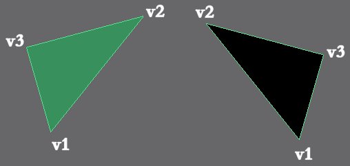
Mesh A mesh is a collection of vertices and faces, forming an object of some sort. This can be a box, a sphere or something very complex. Both objects in the picture above are meshes. Backface culling To remove unnecessary rendering times, the 'back' of a face is not rendered. Why? Well, it is usually pointing into the inner parts of the model so you wouldn't see it anyway. As mentioned before, a face is made up of 3 vertices (call them v1, v2 and v3). The front side of the face is then the side you see when they are placed in a counter clockwise order.
In the picture below, the left face's vertices are ordered in a counter clockwise order, thus making the face visible (from our point of view). The right face's vertices are ordered in a clockwise order, so we can't see it.
If this is confusing, skip it. This is only critical information when placing separate faces to the model. If you're only using primitive shapes (like boxes and spheres) to make up your model then don't mind this. Bone When animating the model, you use so called bones. A bone functions pretty much like bones in the 'real world'. The bones are attached to each other at specific spots, and can not be detached. When you move, the bones affect each others. If you raise your leg the foot follows and so on. It is the bones that you animate when doing an animation. Each bone have some vertices attached to them so the actual model is also animated. You could see this as the flesh and skin follows the bone when the bone moves on a human being. Helper Helpers are also used in animation. I haven't used these in animation, so I can't really say what their purpose is. They seem like static 3D points (bones are vectors, 3D points with a direction). Helper points are also used for attachment points. More on this further down. Introduction First of all i would like to point out one thing - Save Often!!! This can't be said enough times. You don't want to remake your model if something goes wrong. If it's a bigger modeling project, save as different versions in case you accidentally saves a faulty version. This really saves time if something goes wrong. Second, I suggest you read the tutorials that came with GMax. They help you get a basic feeling for GMax - how you navigate in 3D space, creating basic shapes etc... I will only mention some basic operations here. Another thing. In this tutorial I will refer to certain toolbars. To make sure you have them all, right-click right below the menu. A pop up menu will appear. Make sure Command Panel, Tab Panel and Main Toolbar are selected. Looking / Moving around
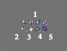
In the bottom right corner there are some tools for navigating the scene. Here is a screenshot of them:
1 - Zoom tools
2 - Field of View
3 - Pan
4 - Arc Rotate
5 - Min/Max toggle Basic objects At the top of the screen you will find this toolbar. Select an object then click in any of the viewports to place that shape, or go to the menu Create -> Standard Primitives. You can also select these from the toolbar on the right. Most of the time you will have to specify the dimensions of the object using the mouse then click another time to accept. Sometime more than once (Example: A block: First you specify the base - Width and Height, then you specify the depth). If you use basic shapes, remember to convert it to an editable mesh before exporting it to MDL format. This is done by selecting the object, right click and select Convert to editable mesh. Simple! Note that once you convert an object to an editable mesh, you cannot modify it as it was a box or a sphere anymore (like changing radius and nr of segments). Mesh editing
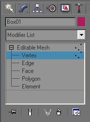
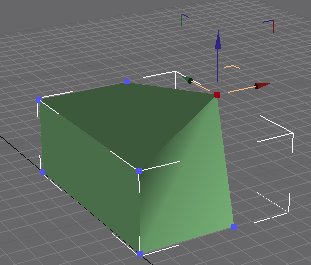
If you have converted an object into an editable mesh (see steps above), you have much more control over its shape. The two most common mesh editings (at least by me ^^) are vertex and face editing. After converting to an editable mesh, select Editable Mesh from the modifiers list to the right, and select the type of editing you want to do.
Vertex editing
Vertex editing allows you to move around single vertices, delete them, add more etc...
You can select any vertex by clicking on the blue dots (representing the vertices). Proper actions for this editing can be found to the right of the screen or by right-clicking when a vertex is selected. Vertex editing is often used to create more advanced objects than simple boxes and spheres.
Face editing
Face editing allows you to modify the faces on a mesh, delete them or add more. Click on a face to select it, then use any action you can find in the toolbar to the right or by right clicking while a face is selected. If a face is not 'visible' when looking at a model (it could be inside another mesh) then you should delete it to save rendering times.
A final word When making models, it is always a good idea to keep the face count low. If not, it will lag incredibly in game if you have many models (units/doodads/whatever) on the screen. It is easy to add more and more details to the model, and using spheres with 64 segments just cause it 'looks good' but try to avoid this. Let the tiny details be in the textures, not the model. Study other people's models (like Blizzard's) to see how they solve this, and make tricks to keep the face count down. Checklist
Editable meshes
Hey, my model is inside-out The material navigator So we've arrived at the texturing tutorial. First of all you need to make a texture. That is something I won't cover in this tutorial. If you need tips on how to make textures, export one of the existing ones from the Warcraft MPQ's, or make a post in the Skinning forums. As a model in this tutorial, I used a simple box.
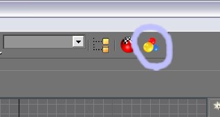
First you have to assign a texture to your model. Open up the Material Navigator by clicking this button in the upper part of the screen:
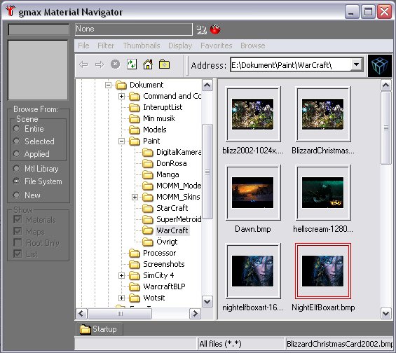
You now enter the material editor. On the left side there are some "Browse From" options. Select "File System", then find your texture file in the tree list that appears. It should now look something like this:
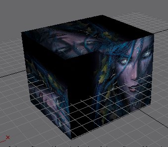
Place the window so you can see both the image you selected and your model. Then simply drag the image from the material editor onto your model. The texture will be placed on your model. If you want the same texture on several meshes, make sure you dragged it once to any mesh first. Then find that material in the navigator and drag it from there to the other meshes. If you drag from the file-view to all meshes directly there will be 1 material created for each mesh, which would be a waste. In the viewport, you'll see which part is textured and which is not. In my example here, I dragged a Nightelf picture onto a box. It now looks like this:
UVW Unwrapping Also see our Unwrap UVW tutorial for step by step details. Now, this is not the prettiest texturing. The whole image is put on each side of the box. What we want to do now is assign only a part of the texture to the sides. This is called UVW mapping. Each vertex has a texture coordinate telling where in the texture it should be. U and V is the same as X and Y coordinates. W is never used. the coordinates are expressed as a percentage, meaning 0,0 is in the top left corner and 1,1 is in the bottom right corner.
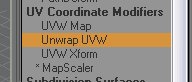
Now, select the model and go to the modifiers list (the one to the right). Scroll down until you reach the UVW Coordinate Modifiers category and select Unwrap UVW.
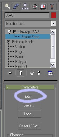
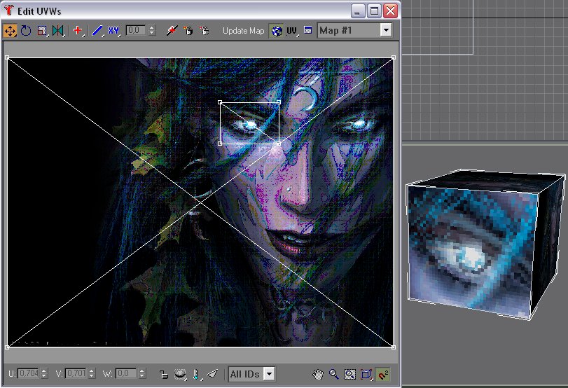
You now have an Unwrap UVW modifier. Expand the tree by clicking on the + and Select face. Then select Edit as shown in the picture below.
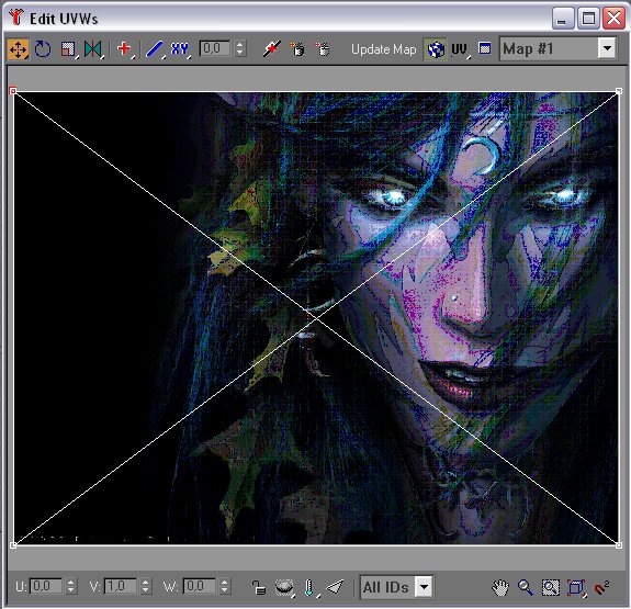
A window will now pop up showing your image and the vertices for your selected mesh. Now simply move around the vertices until they are in the correct place of the texture.
(the image looks like crap, I know. Dunno why! I guess it's too big) This step can be a little difficult as it's hard to pick the 'right' vertex when several lies on top of each others, or the mesh contains so many vertices that it's overwhelming. Make sure you keep an eye on the model in the Perspective viewport all the time to keep track on the result. There is a button in the lower right of the window called Texture snap. Having this selected will make it easier to align the vertices better.
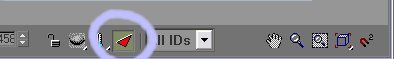
Another nice feature is the Filter Selected Vertices, which can be turned on/off by clicking the triangle-like button at the bottom of the screen. When it's on, only the currently selected face's vertices will show up. Select a face in the 3D view, then edit it in the UVW window. Note that several faces usually share the same vertices.
As an example, I put only the eye of the Nightelf on one of the sides of the box. Drag the proper vertices (they can be hard to find, I know) and form a rectangle around the eye. The texture may appear mirrored or up-side-down, but that can be fixed by moving the vertices around. You can also right-click and select Rotate or Scale the vertices instead of Move which is default if you have need of those operations. Just remember to select some vertices before doing those operations ^^.
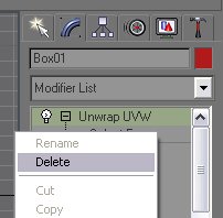
If you accidentally screw up the UVW mapping (will happen, trust me ^^ ) then don't despair. Undo is your friend. Should you screw up things completely, simply select the UVW modifier from the list, right click on it then select delete. Then repeat the above steps again.
Making a texture Though the model looks nice and textured in GMax, it won't be in the game unless you do a texture manually. Start by using the texture you used in the UVW unwrapping process. Convert it to a Targa file (*.tga) using your favorite image editor. Make sure you add an alpha channel also, or it might not work in-game. To add an alpha channel in Paint Shop Pro, do this:
Now you have a Targa file. All you need to do is convert it to a Blizzard Picture (*.blp). Open Image Extractor II. Select the menu "Open" -> "Image" and find your tga file. Open it. Now go to the menu "Save" -> "Image" and save it as a blp file (select blp filter in the dropdown menu). Now, all you have to do is import this into your map together with your model. More on this later. Checklist
Alpha channels
Do you get a "Vertex SkinCount::Skin" error? How does animation work? All animations in a model is in fact one big animation, only you specify which intervals are used for one specific animation. For example, "Stand" can be the interval 0-100, "Attack" can be 140-1200 etc... When making the animations, you can leave some empty space in between them. You don't have to start the second animation directly after the first. In the example above, there are 40 'empty' frames between the "Stand" and the "Attack" animation. It can be good to leave some space in case you want to make one of the first animations a little longer. Notice that you can't name the animations anyway want. Only reserved names like "Stand", "Attack", "Walk" etc... works (as far as i have tested). You can made additional forms of these animations, like "Stand open", "Stand alternate" and such. This will cause that "Stand" animation to be randomly selected. Creating bones
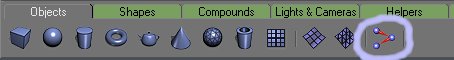
To create a bone, select Bones IK chain from the Objects tab at the top of the window. Click somewhere on the grid and you'll start placing the bone. Click somewhere else and the second point for the bone is placed. Keep placing them depending on how many you want in the chain. You can place just 1 too if you like. Press ESC to stop placing them. One final tiny bone will be created. If you don't want it, select it then press Delete.
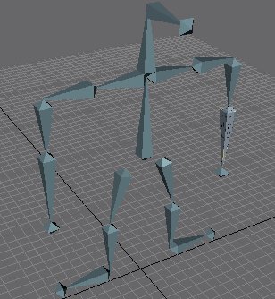
When you create the bones, make sure you place them logically. Look at your model. What parts should move and what parts should be stiff. You can also connect bones together, making them 'stuck' so you can't place them in any weird ways (like placing the leg 10 meters to the left of the head). To connect them, create one on top of another and they will be automatically connected. Out of experience I know that getting chained bones to work is a pain in the @ss. Sometimes no keyframes aren't created at all. When animating chained bones, make sure the little key-icon at the bottom of the screen is selected. I believe this creates keyframes when handling chained bones (not sure).
You may want to name the bones so you can easily find them later. Select a bone, right-click and select properties. Enter a descriptive name so you know that name refers to that bone. This will be important later. Attaching skin to the bones
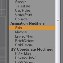
When you move the bones, you probably want the meshes to follow it. It is time to attach the meshes to the bones. Select a mesh (your model probably consists of several, so repeat this step for each of them) then select Modify -> Modifier list -> Animation modifiers -> Skin.
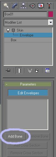
You want your mesh (skin) to be attached to a bone, so select Envelope under the skin modifier, make sure Edit Envelopes is selected (sometimes it is, sometimes not). The click on Add Bone. This will bring up a window with a list of all bones. Select the bone from the list (this is why you should name them so you can find them easily) then click Ok. Don't touch any of the other stuff unless you know what you're doing.
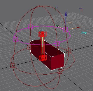
A selection-kinda-something shows up (an envelope). Drag in it until it completely covers the mesh. This can be seen by the mesh turning all red. It doesn't matter if the envelope includes other meshes, since it is only the mesh you added the skin modifier on that is affected. Don't mind the inner envelope selection.
When done, exit the envelope mode by deslecting Envelope to the right. A piece of friendly advice: Out of experience I know that this skin modifier is very unstable. Make safety copies of your model before adding one. If the script doesn't compile or you experience some sort of 'weirdness' in-game, redo the skin modifier. Animation setup
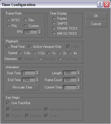
Warcraft 3 uses a framerate of 960 frames per second. To set this up, click on TimeConfiguration (the clock at the bottom of the screen) and enter 960 as the FPS.
Make sure you select Custom too, your number won't affect the framerate otherwise. Set the Start Time to 0 and End Time to whatever you want. Every 960 gives 1 second of animation, so 1500 (as I typed below) gives almost 2 seconds of animation.
Time to animate
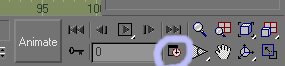
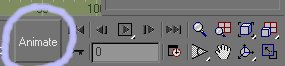
Now it's time to start animating our model. Start this by pressing Animate at the bottom of the screen. This will make the window a little more red indicating that you are now in animate-mode.
When animating you only move the bones of the model. Do NOT move the meshes arond or you will screw up your model. To make it easier you can hide everything except for the bones by selecting the Display Tab to the right then select Geometry under Hide by Category. What you do in animation is set the bones in certain key positions, and the engine will then calculate all the frames in between automatically using interpolation. Why? To save time for you. You wouldn't want to set the bones' positions for every frame. That could be 1000's of frames in total ^^.
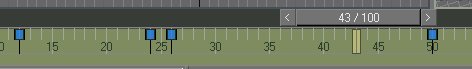
Each key in the animation is represented through 'blocks' in the time-bar at the bottom of the screen. Each block represents either a movement, rotation or a scaling.
If you create a position key, the bone will move to that key from the position key before it (or the beginning).
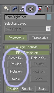
To create a key, select the Motion tab to the left, then select Position, Rotation or Scale under Create Key. This will also create a box on the time slider which you can delete at any time. You can also select the bone and apply any of these translations directly by right-clicking on it and selecting Move, Rotate or Scale.
If you created bones that are attached to each other, the translations may not always create a key on the time slider when rearranging them. I have not found any way to remove a key created in this way. Make sure you don't screw up by making safety copies of the file and/or keeping your finger over the Undo button all the time ^^. When you're done animating, remember to turn off the Animate button. Making a camera
If you would test the model at this point, you would most likely see jibberish in the portrait at the bottom of the screen (inside Warcraft 3). What you want to do is create a camera. At the top of the screen, select Target Camera (it HAS to be a target camera, no other type) then click and drag somewhere to create the camera. Don't create more than 1 camera.
There are two points in the camera, one telling where the camera is and one where the camera is looking at. Move these around until they are placed where you want them. Later when running the script, make sure the camera is selected too.
Checklist
Animate button
I animated my model but it isn't animated in-game?
Speed too fast/slow in-game? What are particle emitters? Particle emitters can only be created by 3DS Max. For other models, you have to add them in by hand. Below is a tutorial for adding particle emitters to your model, by editing the MDL file. ChoBoMapper's Guide To Particle Emitters What are attachment points? Attachment points are used to specify certain points on a model. Like if you want to create a special effect then you can attach it to one of these points. Or if you cast a spell on the unit (which have the model) sometimes a sfx is shown up, like Inner Fire creates a icon at the Overhead attachment point of the unit. Adding the points
In GMax select the Point Helper tool and place the points wherever you want them.
Select the points, right-click and select properties. To actually make them attachment points, you have to name them in the style: ATT:NAME Ref where NAME is the name of the attachment point. An example: ATT:Overhead Ref. Notice that there is no space between ATT: and NAME. Now you're practically done. Make sure the attachment points are selected when running the script. Animated attachment points Logically the attachment point should follow the models movements. So if you have a point at his hand it should follow the hand when it moves. To do this you need to do some MDL editing. First of all, you need to have a bone where the attachment should be (the "bottom" of the bone is where it will be). You may re-use a bone that exists if it located where you want it or you can create a new one. Notice that "lone bones" (bones which aren't attached to a skin modifier) will not be process by the script. If this is a bug, unimplemented feature or simply the way it should be I don't know. however there is a way around this: Create a new bone where you want it to be. Then create a single vertex for a mesh that you have. Then create a skin-modifier for that mesh (unless you haven't already), add the newly created bone to it then make sure it's envelope only surrounds that lone vertex. This bone will now only affect that vertex, and since it is a lone one it will not affect the rest of the model. The bone will be processed since it is attached to a skin modifier. Joy! Now onto the MDL editing. At the bottom of the MDL file you'll find the attachments. It will look something like this: Attachment "Overhead Ref" { ObjectId 4, } To attach it to a bone, add a Parent field and then the ObjectID number that is identified with that bone. If the bone has ObjectID 2, then add Parent 2 to the attachment point. Attachment "Overhead Ref" { ObjectId 4, Parent 2, } Done! Save and convert the file to a MDX. Checklist
I created an SFX on an attachment point on the unit, but it doesn't show up in-game. Exporting the model
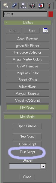
Ok, so now you have your model ready. Eventually animated and textured too (not necessary, though it will only show up in the player's color in game if you don't ^^). Ok, now we're going to export the model from GMax. Select your whole model (or the parts you wish to export). Then click on the Hammer icon in the upper right corner, then select MaxScript. Now click on Run Script.
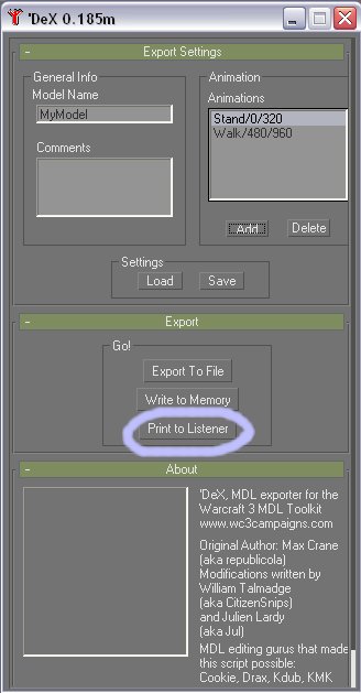
A file browser will open up. Locate Dex's Exporter script (wherever you placed it) and select Open. Another window will be opened. Here you specify a name for your model and which animations it should have. Animations are specified in intervals. For more info on this, read the Animation tutorial above. After that you click on Print to Listener. This will generate the MDL code and place it in the listener window.
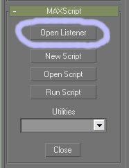
Depending on how big model you have, this process will take some time. If you receive any errors, double check the Checklists in the tutorials above. If an error occurs, GMax usually flips out and behaves really irrational. If this happens, reload your model. DON'T save when it asks you. When done you can open the listener window by clicking on Open Listener to the right.
This will bring up a window with the MDL code in it. Open up an empty Notepad, then copy-n-paste the contents to notepad. There is some kind of bug or something that prevents you from selecting all code at once, so you must copy it piece by piece. DO NOT make a mistake here, or it might screw up the model. make sure you DON'T copy the comments at the beginning and the final line that says "Export successful". There is also an option named Write to Memory, but this is unimplemented in the current version of Dex' Exporter script. After you copied the contents, save it as NAME.mdl (replace NAME with whatever you want). Manual MDL edit Now after saving the file as an MDL, you have to open it with a text editor, and manually edit your materials. Please see our tutorial on how to add your own textures, team color and team glow. MDL -> MDX conversion
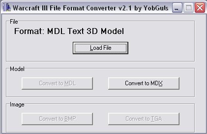
Now you need to convert it to a MDX. This is done using YobGul's converter. Select Load File, set the filter to MDL, find your file and select Open. Now click on Convert to MDX and you're done. A file NAME.mdx is created automatically, where NAME is the same name as in the file NAME.mdl you loaded. be careful you're not accidentally overwriting anything important.
You might get an error message when exiting the converter. Don't mind this. Importing the model into Warcraft 3 Now is the time you've been waiting for all the time. It's time to bring your model into Warcraft 3. Create an empty map or open an existing one. Enter the import manager and import your file. You now have 2 options, either let the model replace an old model by selecting a custom path or let it be the way it is and manually change a unit's/item's/doodad's model in the object editor (Art - Model file). Also, import your texture to the map. Make sure the path is exactly the same as the path you entered in the MDL file. If not, use a custom path to make it right. Don't be afraid if a message saying "the model could not be opened" appears. You will have to reload the map to get the model appear in the editor. It will work ok when running the game, so skip that for now. Now play your map and enjoy! Checklist
Selected meshes
Listener window
Is the model red?
MDL or MDX?
Importer |
||
 |
 |


| Designed by Arkheno
2005 Blizzard Entertainment® Blizzard Entertainment is a trademark or registered trademark of Blizzard Entertainment, Inc. in the U.S. and/or other countries. All rights reserved. |